Since I have had many questions about my DIY MIDI controller for software-based guitar amp and FX simulation, here is a tutorial to explain how to build your own!
MIDI Rack Controller Demo
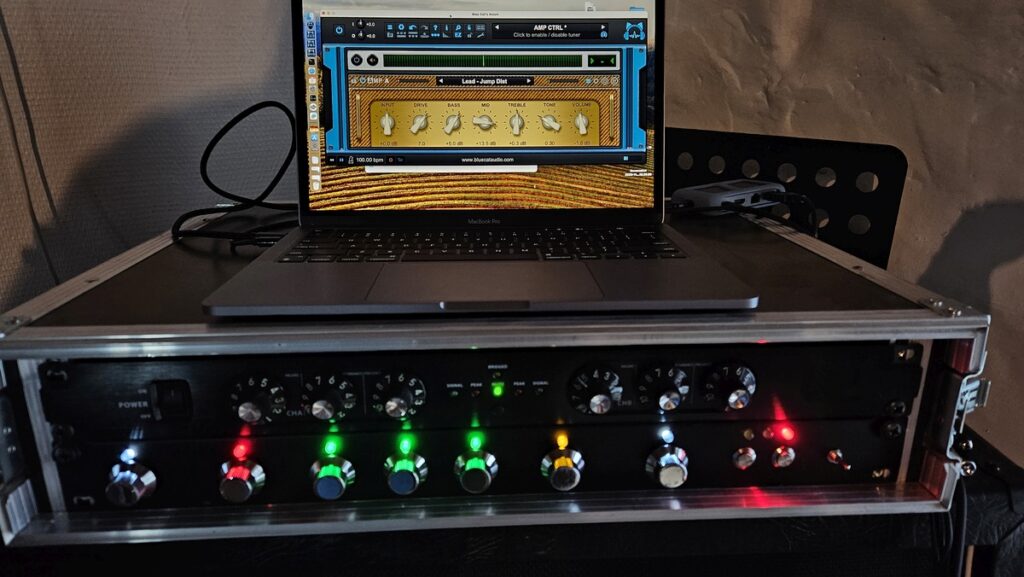
In case you missed it, here is a short demo showing what this DIY MIDI controller for Axiom/Destructor does. In this tutorial we’ll focus on the amp controller (at the top of the rack). The FX controller will be covered in another tutorial (it is actually simpler and very similar).
Background & Requirements
A bit of background information first: in many situations I like to use Axiom a lot as an “old school” 3 channels guitar amp with effect pedals that I activate / tweak live while playing.
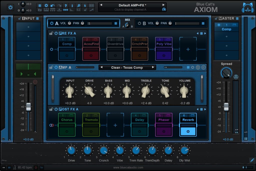
So I needed a MIDI controller that would let me use Axiom’s amp simulation (Destructor) like a traditional amp and fit the controls displayed in Axiom as much as possible: basic gain and EQ controls as knobs, and a channel selector (clean/crunch and lead tones) that can be either activated with a footswitch or buttons on the amp’s face. It would of course be nice to have a color LED to indicate which channel is currently selected.
And independently from this “amp controller”, it would also be nice to have a controller that fits Axiom’s pedalboard/rack design in the new EZ view, with bypass buttons for all effects (with a color LED to show status) as well as knobs for macro controls that I usually use to change the main parameters of the effects:
When doing demos of Axiom, I often need to switch between the controller and the screen, modifying parameters either via MIDI or within the software. I also use another MIDI foot controller to switch effects on and off, so it is necessary that my custom MIDI controller works both ways: when changes are made on the controller, it updates the software, and when changes are made in the software or other controllers, the MIDI controller gets updated (Axiom V2 lets you do that if the controller supports it).
Unfortunately I could not find any MIDI controller that fits all these requirements and look good enough to be used as a controller for guitar amps and effects (yes, look and feel is important, especially on stage!). So after years of research and testing any possible MIDI controller available, I finally decided to build my own!
Disclaimer: I am definitely not an electronics engineer, and this thing was my first-ever microcontroller prototype so it’s not designed to be a “product” in any way :-). The great thing with microcontrollers is that the electronics part can be reduced to its minimum while everything is done with software.
Technical Design
Hardware
Since I already use an FRFR power amp that can be placed in a 19” rack, it seemed obvious that both controllers should use the rack format. I used two independent metallic 1U face plates for this purpose, as all knobs and buttons should fit in there easily:
The only issue is that drilling metal when you do not have the right tools (a column drill in this case) is quite painful… I tried it for you! So if you want to make it easy, you should probably go for a wood plate instead (it should be pretty easy to do it yourself).
Encoders

To be able to update the controller from the software via MIDI you cannot use regular knobs (unless they are motorized, but there are very few available and their cost is prohibitive), so I chose to go with rotary encoders (that you can turn indefinitely in either direction). There are plenty available on the market – just make sure not to get the cheapest or they will probably fail after a few turns. Also, make sure that you get encoders with good precision. I think I ended up using 24 impulses encoders without dents (I initially though dents would be nice to know precisely how parameters are being updated but it’s noisy and I definitely prefer the smooth ones).
Since most of them also provide a press button, why not use it as way to reset the current knob to default value? In the end I think this was a bit too much hassle, as I don’t use this feature at all :-).

I thought it would be nice to be able to see the position of the knob on the rack. You can find some LED rings to place around the encoders for this purpose, but drilling so many small holes in the face plate was just not an option. So I ended up trying single LEDs which intensity vary with the value (the brighter the higher the value). It’s fun, but it looks a bit like a Christmas tree and I actually do not use it at all since I can see the position of the knobs on the screen… So in version 2 I’ll get rid of the useless LEDs and save many pins on the Teensy!
Switches
As mentioned earlier, I need 2 momentary switches to toggle between channels, and another up/down momentary switch to navigate thru amp banks (it could be presets too). These have to be momentary switches as the microcontroller will be triggered by impulses. This way the buttons themselves are stateless, which is necessary if you want to update the controller’s state from the outside.

Microcontroller
The main component to manage buttons, knobs LEDs etc. is the micro controller, which transforms knob movements and switch presses into MIDI that is transmitted to the computer via USB. After a bit of research, I ended up using a Teensy 4.1 controller for multiple reasons:
- This amp controller needs many inputs and outputs, and the Teensy offers lots of them compared to any Arduino.
- The Teensy controller has MIDI over USB built-in (no need to go for extra libraries), so it is really easy to get started.
- Rotary encoder are complex beasts, and work best with interrupts, which are available on all input ports on the Teensy, so why bother with other methods?
- The Teensy is very powerful, so there is a lot of headroom if I ever want to do anything more complex with it (audio for example). It has an incredibly powerful 700 MHz ARM processor.
- It is powered via USB so you just need to connect it to a laptop to power it up.
If you get rid of the extra LEDs and reset buttons as explained earlier, you can save many pins and it would probably fit into a Teensy 4.0 microcontroller, which is cheaper and smaller (with the exact same features).
Amp Controller Features
Before getting into the steps to build it, here is the full feature list for the controller:
- Rotary Controls: Input Volume, Gain, Bass / Mid / Treble / Tone and Master Volume (as displayed in Axiom). Note for V2: I never use the input and output volume knobs, so they will probably be removed at some point!
- For each rotary control, a LED which brightness shows the current value (to be removed in V2 as explained earlier). Using different colors should help visualize the various controls from far away.
- A clean/crunch and a clean/lead toggle button as well as 3 LEDs to display the selected channel (Clean/Crunch/Lead). This sends a Program Change message to the Destructor amp in Axiom (0-Clean preset / 1-Crunch preset / 2 – Lead preset)
- Since there is room left and I like to change amps from time to time, let’s add an up/down mini-switch to switch amp presets banks (I use banks for separate models, each bank containing the clean, crunch and lead presets). It can also be used to iterate over amp presets in Axiom.
Hardware
That’s the most difficult part when you do not have the right tools (which is often the case for a prototype, and as a software company, that’s not the kind of tools that are available in the office!). After marking the positions for all components, it’s “just” a matter of drilling the holes:
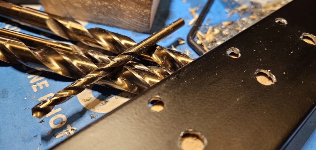
And then put the components in place:

Once everything is in place, the components are soldered to the microcontroller using wires (a PCB would definitely be nicer, but for a prototype you probably do not want to bother), and all ground pins are soldered together:
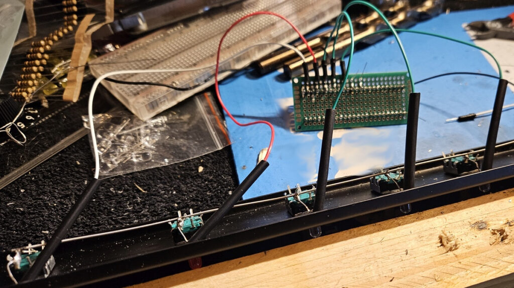
Note about noise: although we are not processing audio with the controller, it is connected to the computer via USB, so noise may be induced into the audio interface thru this connection. It is thus important to avoid ground loops and leakage currents.
Rotary encoders require two input pins plus the ground. The optional reset switch uses an extra pin. LEDs only require one output pin plus the ground (don’t mess with polarity!). Since there is no PCB, the LEDs will be kept in place by the fact that they are soldered onto the encoders’ pins:

In order to protect the LEDs, I have added a resistor for each one in series wit the LED at the output of the controller. The value depends on the characteristics of the LEDs, but 100 to 200 Ohms will typically do the trick:

Momentary switches require one input pin and the ground. The up/down switch can be considered as two combined momentary switches. Middle pin to the ground and two others connected to input pins on the microcontroller.
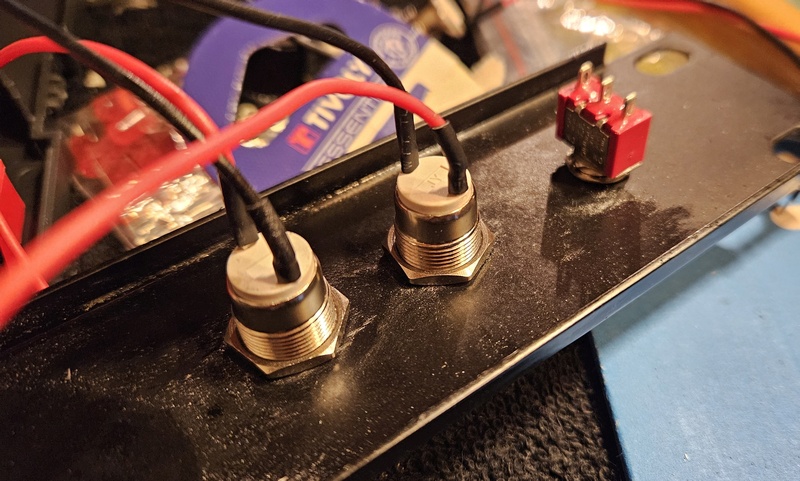
In order to troubleshoot the device, I am using the built-in LED (there is a LED on the PCB for this purpose) to show MIDI activity, but that’s definitely optional and not useful for the controller once built.
That’s it. As you can see, for the moment it is only a matter of connecting the components pins to the ground or input / output pins on the controller (+resistors for the LEDs). Nothing fancy in terms of electronics!
Software
What’s nice with Arduino-style microcontrollers is that most of the work happens in software. Once everything is connected, all the logic happens with software that is sent to the board via USB. In this case, the software layer is pretty thin, managing a few MIDI events that are exchanged via USB, and interfacing with a few rotary encoders, LEDs and switches.
What takes time is mainly to double check the pin numbers for each component. Thanks to built-in Encoder and Bounce classes to manage encoders and switches, the rest is pretty straightforward as you will see in the code below.
Like for an Arduino controller, components are initialized in the setup routine, then the main loop is called as often as possible by the processor. That’s where we read the MIDI events and update the state of the controls, and send MIDI thru USB upon changes.
Note about noise: LEDs brightness is controlled via PWM, which produces electromagnetic waves that will be caught by your guitar pickups. Adding the following line for LEDs pushes the PWM outside of the hearable range:
analogWriteFrequency(ledPin,90000); ///< frequency outside of hearable range
After testing a couple of ranges and increments for the encoders, I found that it would be useful to have to resolutions: a lower resolution when turning the knobs fast and a better resolution for precision when turning the knobs slowly. This is implemented with the help of the built-in elapsedMillis utility.
Source Code
Here is the full source code for the MIDI controller, also available on GitHub here. As you can see it’s not very long.
#include <Bounce.h>
#include <Encoder.h>

/** Interface for MIDI-controllable controls
*   such as rotary encoders, sliders etc.
*/
class ICustomControl
{
public:
  /// called when MIDI value received from USB
  virtual void OnMIDIValue(uint8_t value)=0;
  /// returns the MIDI value stored in the control
  virtual uint8_t GetValue()const;
  /// update the value from hardware
  virtual bool Update()=0;
};

/** class to manage an encoder and its display LED.
*   - pin1,pin2: encoder pins.
*   - iLedPin: the pin for the brightness LED.
*   - iResetPin: the pin for the reset button (resets to default value set by defaultPos).
*/
class EncoderWithLed : public ICustomControl
{
  public:
  static const int kCountRatio=4;
  static constexpr float kPWMRatio=.8;
  EncoderWithLed(uint8_t pin1,uint8_t pin2,uint8_t iLedPin,uint8_t iResetPin,int defaultPos=0):
   defaultPosition(defaultPos),
   encoder(pin1,pin2),
   pushButton(iResetPin,20), // 20 ms bounce
   ledPin(iLedPin),
   currentPosition(defaultPos),
   encoderDelta(0)
  {
      pinMode(ledPin,OUTPUT);
      analogWriteFrequency(ledPin,90000); ///< freq to be outside of hearable range
      pinMode(iResetPin,INPUT_PULLUP);
      encoder.write(0);
  }

  // MIDI CC callback
  virtual void OnMIDIValue(uint8_t value)
  {
      // update current position and reset encoder
      currentPosition=value;
      encoder.write(0);
      encoderDelta=0;
  }

  virtual uint8_t GetValue()const
  {
      return currentPosition;
  }

  // local update
  virtual bool Update()
  {
    int oldPosition=currentPosition;

    // check encoder for param change + check boundaries
    int delta=encoder.readAndReset();
    encoderDelta+=delta;
    if(abs(encoderDelta)>=kCountRatio)
    {
      int actualDelta=encoderDelta/kCountRatio;
      encoderDelta-=actualDelta*kCountRatio;
      if(actualDelta!=0)
      {
        // compute how fast the encoder has been turned.
        // fast turn? increase delta (5 times actual delta)
        int elapsedMs=elapsed;
        elapsed=0;
        if(elapsedMs/abs(actualDelta)<100)
          actualDelta*=5;

        currentPosition+=actualDelta;

        // bounds checking
        if(currentPosition>127)
          currentPosition=127;
        if(currentPosition<0)
          currentPosition=0;
      }
    }

    // check button for reset
    if(pushButton.update())
    {
      if(pushButton.fallingEdge())// button pushed -> reset to default
      {
        currentPosition=defaultPosition;
        encoder.write(0);
      }
    }

    // update led - adjust brightness via PWM ratio according to position
    analogWrite(ledPin,int(currentPosition*kPWMRatio));/// PWM 0 to 255
    return currentPosition!=oldPosition;
  }
  int defaultPosition;
private:
  Encoder encoder; ///< the encoder
  elapsedMillis elapsed; ///< timer to check rotation speed
  Bounce  pushButton; ///< the reset to default button
  uint8_t ledPin; //< the LED to show value
  int currentPosition; ///< the current MIDI position of the encoder
  int encoderDelta; ///< how much has the encoder moved since last update?
};

/** Utility class to manage the Amp channels: clean/crunch/lead.
*   - switch1Pin: the pin for the switch to toggle between clean and crunch.
*   - switch2Pin: the pin for the switch to toggle between clean and lead.
*   - led1/2/3: leds for channels 1/2/3
*/
class AmpChannelManager
{
  public:
    AmpChannelManager(uint8_t switch1Pin,uint8_t switch2Pin,uint8_t led1,uint8_t led2,uint8_t led3):
    crunchButton(switch1Pin,30),
    leadButton(switch2Pin,30),
    currentProgram(0),
    led1Pin(led1),
    led2Pin(led2),
    led3Pin(led3)
    {
      pinMode(switch1Pin,INPUT_PULLUP);
      pinMode(switch2Pin,INPUT_PULLUP);
      pinMode(led1Pin,OUTPUT);
      pinMode(led2Pin,OUTPUT);
      pinMode(led3Pin,OUTPUT);
      digitalWrite(led1Pin,LOW);
      digitalWrite(led2Pin,HIGH);
      digitalWrite(led3Pin,LOW);
    }

    bool Update()
    {
      int oldProg=currentProgram;
       // check buttons updates
      if(crunchButton.update())
      {
        if(crunchButton.fallingEdge())// button pushed -> toggle betwwen prog 0 and 1
        {
          if(currentProgram!=1)
            currentProgram=1;
          else
            currentProgram=0;
        }
      }
      else if(leadButton.update())
      {
        if(leadButton.fallingEdge())// button pushed -> toggle betwwen prog 0 and 2
        {
           if(currentProgram!=2)
            currentProgram=2;
          else
            currentProgram=0;
        }
      }

      // update LEDs state
      switch(currentProgram)
      {
        case 0: // Clean
        {
            digitalWrite(led1Pin,LOW);
            digitalWrite(led2Pin,HIGH);
            digitalWrite(led3Pin,LOW);
            break;
        }
        case 1: // Crunch
        {
            digitalWrite(led1Pin,HIGH);
            digitalWrite(led2Pin,LOW);
            digitalWrite(led3Pin,LOW);
            break;
        }
        case 2: // Lead
        {
            digitalWrite(led1Pin,LOW);
            digitalWrite(led2Pin,LOW);
            digitalWrite(led3Pin,HIGH);
            break;
        }
      }

      // has it changed?
      return currentProgram!=oldProg;
    }

    uint8_t GetValue()const
    {
      return currentProgram;
    }

    private:
    Bounce crunchButton;
    Bounce leadButton;
    uint8_t currentProgram;
    uint8_t led1Pin;
    uint8_t led2Pin;
    uint8_t led3Pin;
};

/** Utility class to manage selected bank (using up and down switch).
*   switch1Pin: pin for the up switch.
*   switch2Pin: pin for the down switch.
*/
class BankSelector
{
  public:
    BankSelector(uint8_t switch1Pin,uint8_t switch2Pin):
    upButton(switch1Pin,30),
    downButton(switch2Pin,30),
    currentBank(1)
    {
      pinMode(switch1Pin,INPUT_PULLUP);
      pinMode(switch2Pin,INPUT_PULLUP);
    }

    bool Update()
    {
      int oldBank=currentBank;
       // check buttons updates
      if(upButton.update())
      {
        if(upButton.fallingEdge())// button pushed -> increase bank #
        {
          if(currentBank<127)
            currentBank++;
        }
      }
      else if(downButton.update())
      {
        if(downButton.fallingEdge())// button pushed -> decrease bank #
        {
          if(currentBank>1) // only using user banks (skip 0 which contain factory presets)
              currentBank--;
        }
      }
        return currentBank!=oldBank;
    }

    uint8_t GetValue()const
    {
      return currentBank;
    }

    private:
    Bounce upButton;
    Bounce downButton;
    uint8_t currentBank;
};

// Setup MIDI channel here
const int kMIDIOutChannel=1;
const int kMIDIInChannel=1;

// Setting up the control pins, as connected to the controller
EncoderWithLed inKnob(22,23,0,1,63);
EncoderWithLed driveKnob(20,21,2,3);
EncoderWithLed bassKnob(18,19,4,25,63); /// TBD 0 or other
EncoderWithLed midKnob(16,17,6,5,63);
EncoderWithLed trebleKnob(14,15,8,7,63);
EncoderWithLed toneKnob(40,41,10,9,42); // default ~.3
EncoderWithLed outKnob(38,39,12,11,63);

EncoderWithLed* encoders[7]={&inKnob,&driveKnob,&bassKnob,&midKnob,&trebleKnob,&toneKnob,&outKnob};
AmpChannelManager ampSelect(31,32,24,28,33);
BankSelector bankSelect(30,29);

// elapsed time / used to reset the test LED that shows MIDI activity
elapsedMillis elapsed;

// On MIDI CC input callback
void onCC(byte channel, byte control, byte value)
{
  // toggle built-in LED for MIDI activity and reset elapsed time.
  digitalToggle(LED_BUILTIN);
  elapsed=0;

  // MIDI channel and control # ok? set encoder value
  if(channel==kMIDIInChannel && control>0 && control<=7)
  {
    encoders[control-1]->OnMIDIValue(value);
  }
}

// setting up
void setup() {
  usbMIDI.setHandleControlChange(onCC);
  pinMode(LED_BUILTIN,OUTPUT);
}

// main loop
void loop() {
  // get MIDI in (calls MIDI CC callback if any event arrived)
  usbMIDI.read();

  bool midiSent=false;

  // update encoders from hardware
  for(int i=0;i<7;i++)
  {
    if(encoders[i]->Update())
    {
      // if changed send MIDI
      usbMIDI.sendControlChange(i+1,encoders[i]->GetValue(),kMIDIOutChannel);
      midiSent=true;
    }
  }

  // update bank selector
  if(bankSelect.Update())
  {
      if changed, send MIDI
      usbMIDI.sendControlChange(0,bankSelect.GetValue(),kMIDIOutChannel);
      usbMIDI.sendProgramChange(ampSelect.GetValue(),kMIDIOutChannel);
      midiSent=true;
  }

  // update amp channel selector
  if(ampSelect.Update())
  {
    // if changed, send MIDI
    usbMIDI.sendProgramChange(ampSelect.GetValue(),kMIDIOutChannel);
    midiSent=true;
  }

  // update MIDI I/O led
  if(midiSent)
  {
    digitalToggle(LED_BUILTIN);
    elapsed=0;
  }

  // make sure the light ends up being shut down after 500 ms without any MIDI activity
  if(elapsed>500)
  {
    digitalWrite(LED_BUILTIN,LOW);
    elapsed=0;
  }
}
You can customize the name of the MIDI controller so that it does not appear with a generic name as a USB device by adding a name.c c file with the manufacturer/device name definition, as you can see on the GitHub repository.

Step by Step Testing
It is necessary to test the controller at every single step (there may be issues with wiring, soldering, pin numbers or software bugs…). Here is an example while testing banks and presets switching with Axiom.
Add-On: Footswitch Support
It is more convenient to switch amp channels with the foot, so I have added a footswitch connection with an extra stereo jack plug soldered in parallel onto the two momentary switches. This way you can connect a dual footswitch (momentary footswitches required) with a simple stereo jack.
Here the full controller with the extra cable, and USB adapter cable (the micro controller has a mini USB connector, which is not convenient, and you want to be able to connect easily without diving into the rack).
 I’ll definitely add a box or a plate at come point to avoid having the microcontroller floating inside the rack! 🙂
Enjoy!


Regarding the add-on momentary footswitches: should they be normally open or closed configuration?
I think they are open here. But it could be the other way round, as long as your switches are the same. It can be configured in the software (you would just look for the opposite transitions).
I was very interested to find this project as I’m just finishing off my own first design of a MIDI controller for a guitar sim. I also decided to use the Teensy 4.1 and rotary controllers but my controller is set up for the Neural DSP Tone King Imperial Mk II (sorry!)
the design allows control of the nearly 100 variables in the Tone King and has a 6-way (expandable to 12) footswitch bank for selecting presets, plus a rotary switch to select between 12 sets of six presets and an input for an expression pedal.
I’d be interested to compare notes on how best to implement controllers for amp sims in general. It seems to be a neglected niche at the moment.
Kit
Nice! Do yo have any pointer to more information?