Today, let’s have a look at how to build your own DIY MIDI-Controlled USB Analog Vu Meter. It is actually pretty simple (simpler than the amp sim controller), as the device only receives and “shows” MIDI values.
MIDI Analog VU Meter Demo
in case you missed it, here is a quick demo of the controller and how to use it within your DAW with the DP Meter pro plug-in:
It lets you monitor any “in the box” audio signal on physical VU Meters.
Requirements
My goal with this project was to reproduce the VU-Meters that could be found on tape machines in recording studios in the old days to monitor levels from recording software (either a DAW (Digital Audio Workstation) or the Fader Hub application) .
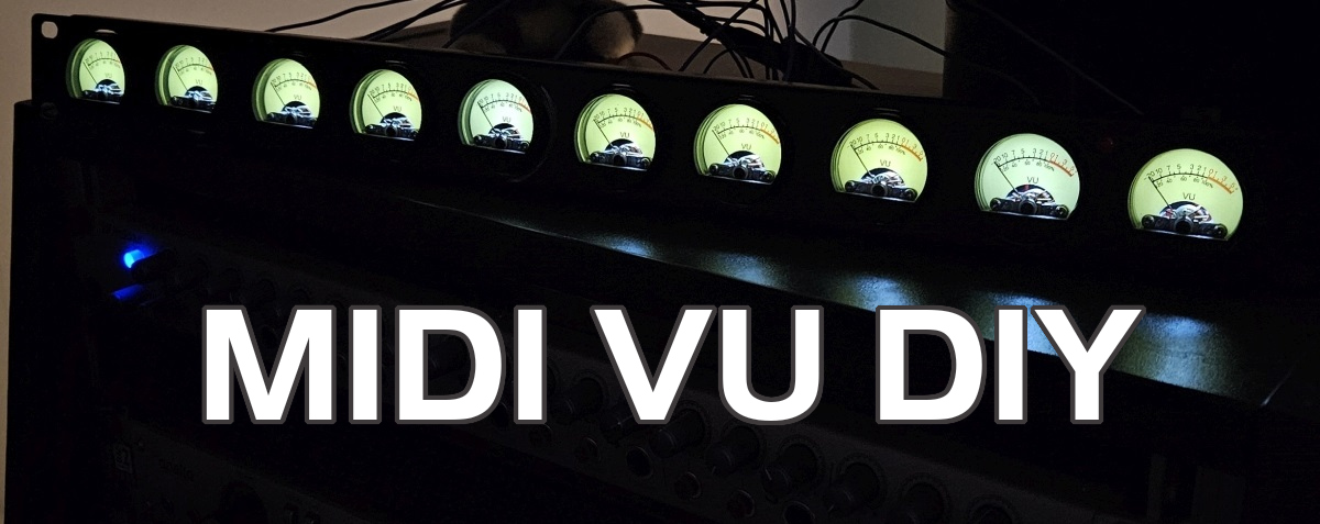
My typical need would be to monitor eight tracks with mono meters, and the master levels (stereo), with a clipping LED in case clipping is detected on either channel of the master bus. This gives a total of 10 VU-Meters to fit in a 1U Rack.
To avoid adding any extra noise to the signals, and to be able to monitor any “In the Box” levels, a MIDI controlled meter seemed like the best solution. And since we already have a plug-in that can send audio levels via MIDI, we just need a piece of hardware to receive the MIDI values and “display” them with real analog VU Meters.
Hardware Choices
The idea here is to use a microcontroller to handle MIDI messages coming from the USB port, and drive analog VU-Meters based on received MIDI values (sent by the DP Meter Pro plug-in for example).
Micro Controller: Teensy 4
Since I have already used the Teensy controller for other projects, that’s the one I chose here (a Teensy 4 this time, as not that many pins are used here). You get MIDI-USB for free, and it is extremely powerful (way too much for this project, actually). You can probably build a cheaper version with a less-capable Arduino without any problem.
VU Meters
You can find many types of analog Vu-Meters on the market. Since the Teensy’s output is 3.3V you need to find meters that accept this type of voltage (5V ones fit perfectly – I don’t think you’d have enough power for 12V meters though).
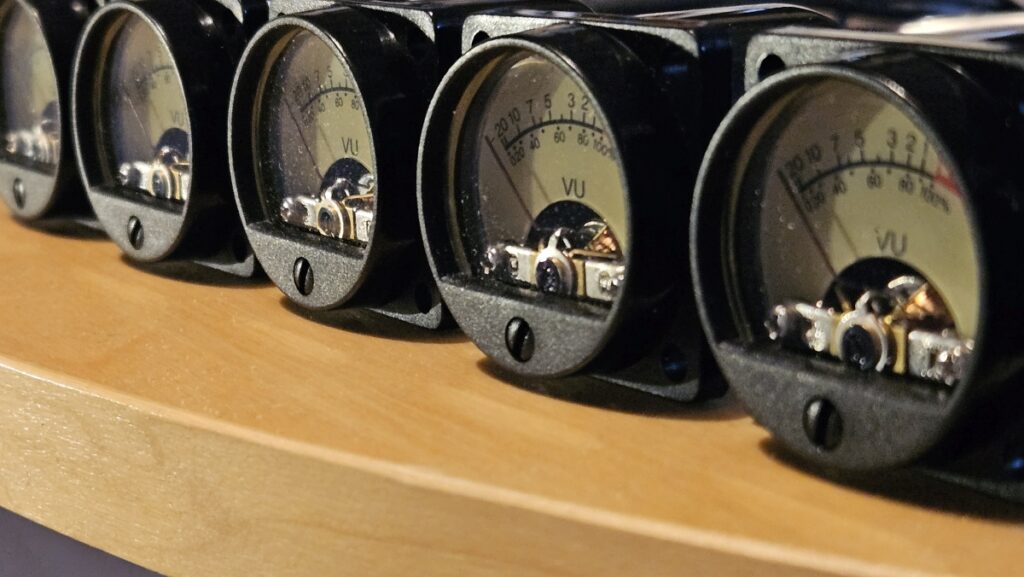
Since I’d like these 10 VU-Meters to fit into a 1U rack, I chose VUs with 35mm diameter. It perfectly fits both vertically and horizontally.
Each VU-Meter has 3 pins: a ground, the pin to get the analog signal to measure, and another pin for the backlight.
Building the VU Meter Rack
Like last time, the most difficult part for me here was drilling the metal rack to make room for the components. Without the proper tools it can be a bit of a challenge. So if you are not ready for that, you should maybe build a wood-based rack/box instead.
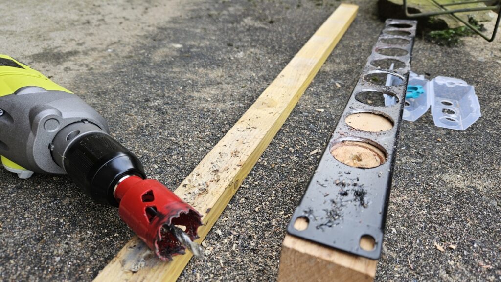
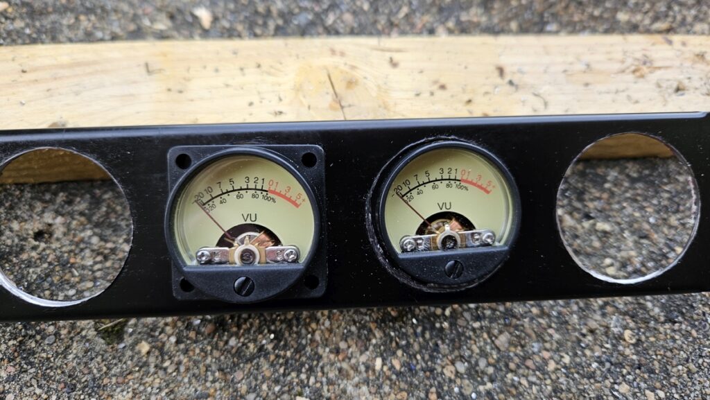
It was initially planned to use screws to attach the meters onto the rack, but I found it actually easier to glue them. Use Polyurethan glue (PU) if you can. It will work much better than any other type of glue (but don’t expect to be able to remove them anymore!).
Once all the meters are in place you can solder the wire to connect the pins to the ground, the backlight pin and individual output pins for each meter:
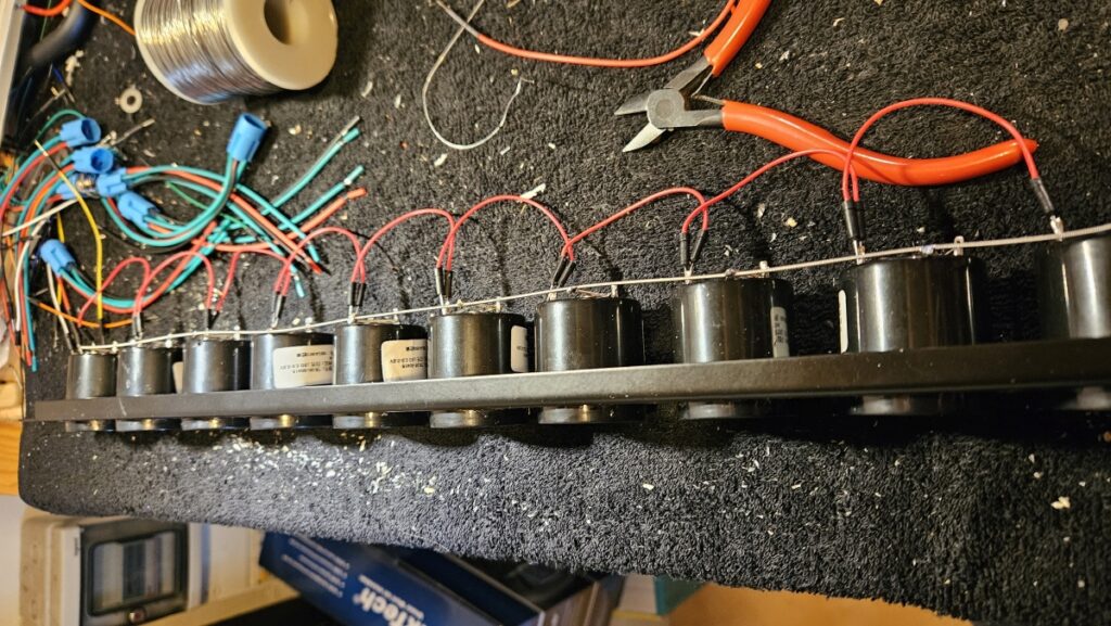
Since the Teensy’s output pins only work with PWM (no actual voltage control), I have added 1μF capacitors between each vu-meter’s voltage pin and the ground to filter the signal:
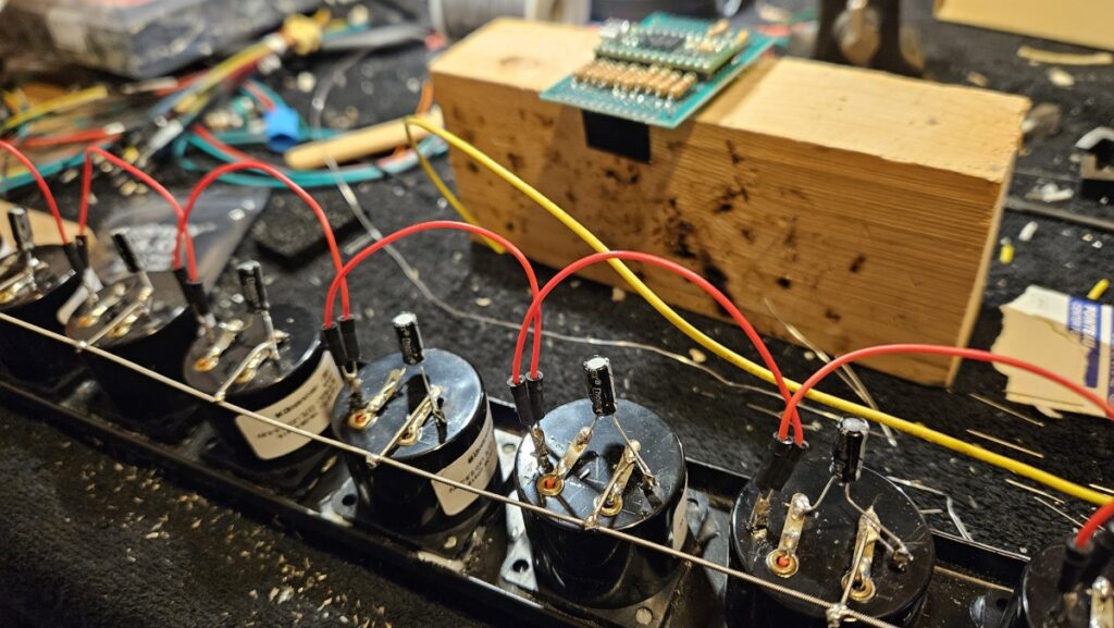
If you don’t do that, you will probably hear buzzing and may damage the VU meters. All VU Meters are also protected with a 5.6kΩ resistor in series. To select this value, I have tested the VU-Meters with large resistors and decreased the value of the resistors until the meter reached the maximum value with a continuous 3.3V input. The required values may vary depending on the meters that you have.
A 150Ω resistor is used in series with the backlight LEDs, which are all wired in parallel to a single PIN on the teensy. If your LEDs are drawing too much current or if you want to be able to light each meter separately you may want to use several pins instead.
And that’s pretty much it for the hardware. The clipping LED is a simple LED protected by yet another resistor, that’s it.
Programming The VU Meter Rack
Basic functionality is straightforward: the device will receive the [0-127] values via MIDI CC and will transform them into PWM signals to control the VU Meters.
There are however a few things to consider. First, since each “track” VU will be used to display either mono or stereo levels, it should be able to receive MIDI values from 2 different CC and compute the maximum before sending it to the analog VU Meter via PWM.
Second, the analog VU Meters have to be calibrated. They are supposed to be voltage-controlled, not with PWM (although it ends up being roughly equivalent), and there is anyway no spec sheet with the actual response of the meter.
The response is not linear, so you have to use a lookup table to scale the values appropriately. With VU-meters, precision is not exactly an issue, so 7 values were more than enough for a 26 dB range!
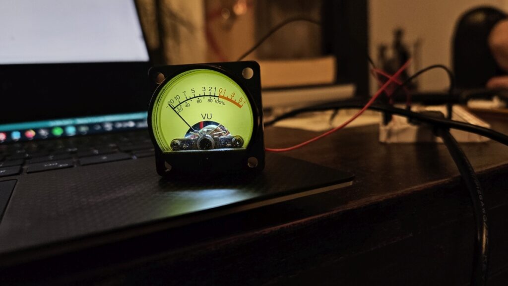
To calibrate the meters and build the lookup table, I have simply tested the meters with static PWM values and reverse-engineered key PWM ratio values from displayed decibel values (the calibration and testing code is commented out in the source code below).
Note about noise: LEDs brightness is controlled via PWM, which produces electromagnetic waves that will be caught by your guitar pickups. Adding the following line for LEDs pushes the PWM outside of the hearable range:
analogWriteFrequency(ledPin,90000); ///< frequency outside of hearable range
Source Code
Here is the full source code for the MIDI VU-Meter. It is also available on GitHub here.
#include <Bounce.h>
#include <Encoder.h>

/** MIDI-controlled analog Vu-Meter handling.
*   Designed to take left and right signals as MIDI input and display the max value.
*   - vuPin: Vu meter output pin.
*/
class VuMeter
{
  public:
  VuMeter(int vuPin):
  pin(vuPin),
  midiValueL(0),
  midiValueR(0)
  {
    pinMode(pin,OUTPUT);
    analogWriteFrequency(pin,90000); ///< freq to be outside of hearable range
  }

  void SetMIDIValueL(int midiValue)
  {
    midiValueL=midiValue;
    UpdateMeter(std::max(midiValueL,midiValueR));
  }
  void SetMIDIValueR(int midiValue)
  {
    midiValueR=midiValue;
    UpdateMeter(std::max(midiValueL,midiValueR));
  }

  void UpdateMeter(int midiValue)
  {
    // Convert [0-127] midi to decibels
    float dBValue=float(midiValue)/127.0*26.0-20.0;

  // POFET Vu - using 5.6k resistor for meter / 150 for lighting
  // + capacitor 1 microF
  // PWM to dB values mapping resulting from calibration:
  // 188 -> +6
  // 123 -> +3
  // 88 -> 0
  // 62 -> -3
  // 36 -> -6
  // 17 -> -10
  // 3 -> -20
  float pwmValue=0;
  if(dBValue<-20)
    pwmValue=0;
  else if(dBValue<-10)
  {
    pwmValue=3+(dBValue+20.0)*(17.0-3.0)/10.0;
  }
  else if(dBValue<-6)
  {
    pwmValue=17+(dBValue+10.0)*(36.0-17.0)/4.0;
  }
  else if(dBValue<-3)
  {
    pwmValue=36+(dBValue+6.0)*(62.0-36.0)/3.0;
  }
  else if(dBValue<0)
  {
    pwmValue=62+(dBValue+3.0)*(88.0-62.0)/3.0;
  }
  else if(dBValue<3)
  {
    pwmValue=88+(dBValue)*(123.0-88.0)/3.0;
  }
  else if(dBValue<=6)
  {
    pwmValue=123+(dBValue-3)*(188.0-123.0)/3.0;
  }
  analogWrite(pin,int(pwmValue+.5));
  }
  private:
  int pin;
  int midiValueL;
  int midiValueR;
};

VuMeter meters[]={VuMeter(11),VuMeter(10),VuMeter(8),VuMeter(7),VuMeter(6),VuMeter(5),VuMeter(3),VuMeter(2)};
VuMeter masterL(1);
VuMeter masterR(0);
bool ledL=false;
bool ledR=false;

static const int kMIDIChannel=16;
#define LED_PIN 16
#define LIGHT_PIN 14
#define VU_PIN 1

void onCC(byte channel, byte control, byte value)
{
  if(channel==kMIDIChannel)
  {
    if(control<=16 && control>0)
    {
      int index=(control-1)/2;
      if(control&1)
        meters[index].SetMIDIValueL(value);
      else
        meters[index].SetMIDIValueR(value);
    }
    else if(control==121)
    {
      masterL.SetMIDIValueL(value);
    }
    else if(control==122)
    {
      masterR.SetMIDIValueR(value);
    }
    else if(control==123)
    {
      // master clip LED LEFT
      ledL=(value>64);
      bool actualValue=ledL||ledR;
      if(actualValue)
        digitalWrite(LED_PIN,HIGH);
      else
        digitalWrite(LED_PIN,LOW);
    }
    else if(control==124)
    {
      // master clip LED RIGHT
      ledR=(value>64);
      bool actualValue=ledL||ledR;
      if(actualValue)
        digitalWrite(LED_PIN,HIGH);
      else
        digitalWrite(LED_PIN,LOW);
    }
    digitalToggle(LED_BUILTIN);
  }
}

void setup() {
  usbMIDI.setHandleControlChange(onCC);
  pinMode(LED_BUILTIN,OUTPUT);
  pinMode(LIGHT_PIN,OUTPUT);
  digitalWrite(LIGHT_PIN,HIGH);
  pinMode(LED_PIN,OUTPUT);
}

void loop() {
  // just read input values from MIDI
  usbMIDI.read();

  /* Test & calibration routine
  for(int i=0;i<8;i++)
  {
    meters[i].SetMIDIValueR(127*(0+20)/26);
  }*/
  /*
  int dB=0;
  meter.SetMIDIValue(127*(dB+20)/26);*/
}
And that’s it for the software! As you can see it’s not rocket science.
Enjoy!



Where did you find these VU meters?
These were found on Amazon.
Is this something you have thought about selling? I’d would buy it with the plugin
That would indeed be fun, but selling hardware is completely different business, that’s why I am sharing the idea and the source code, in case you want to have it built.